DIY build of a gantry milling machine with standalone controller and auto tool change
Home and limit switches
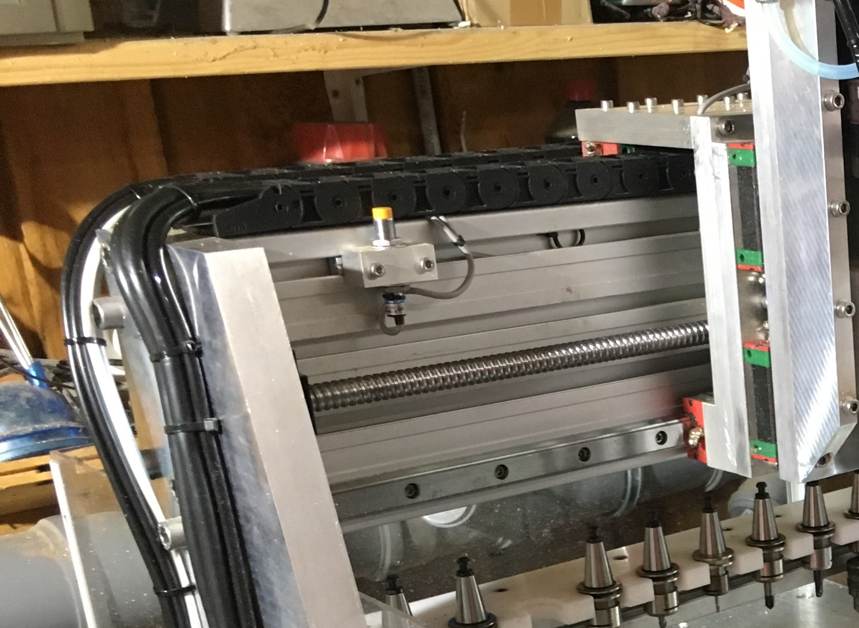
In sum, six limit switches where built into the milling machine, two for both ends of the X/Y/Z axes. I used cheap NPC inductive sensors mounted on blocks, which are fixed in the rails of the aluminum extrusions for the X- and Y axis. For the Z-Axis the sensors are mounted to the X-Plate.
Simple screws served as counterparts of the end switches. For X- and Y direction in fact this is one screw which is used for both directions. By loosing the block screws for the X and Y sensors it is possible to move the sensors to their desired positions to get the exact relative position at both ends.
X-- -Limit (=X-Home) sensor (left image) and corresponding screw on the gantry wagon (right image)
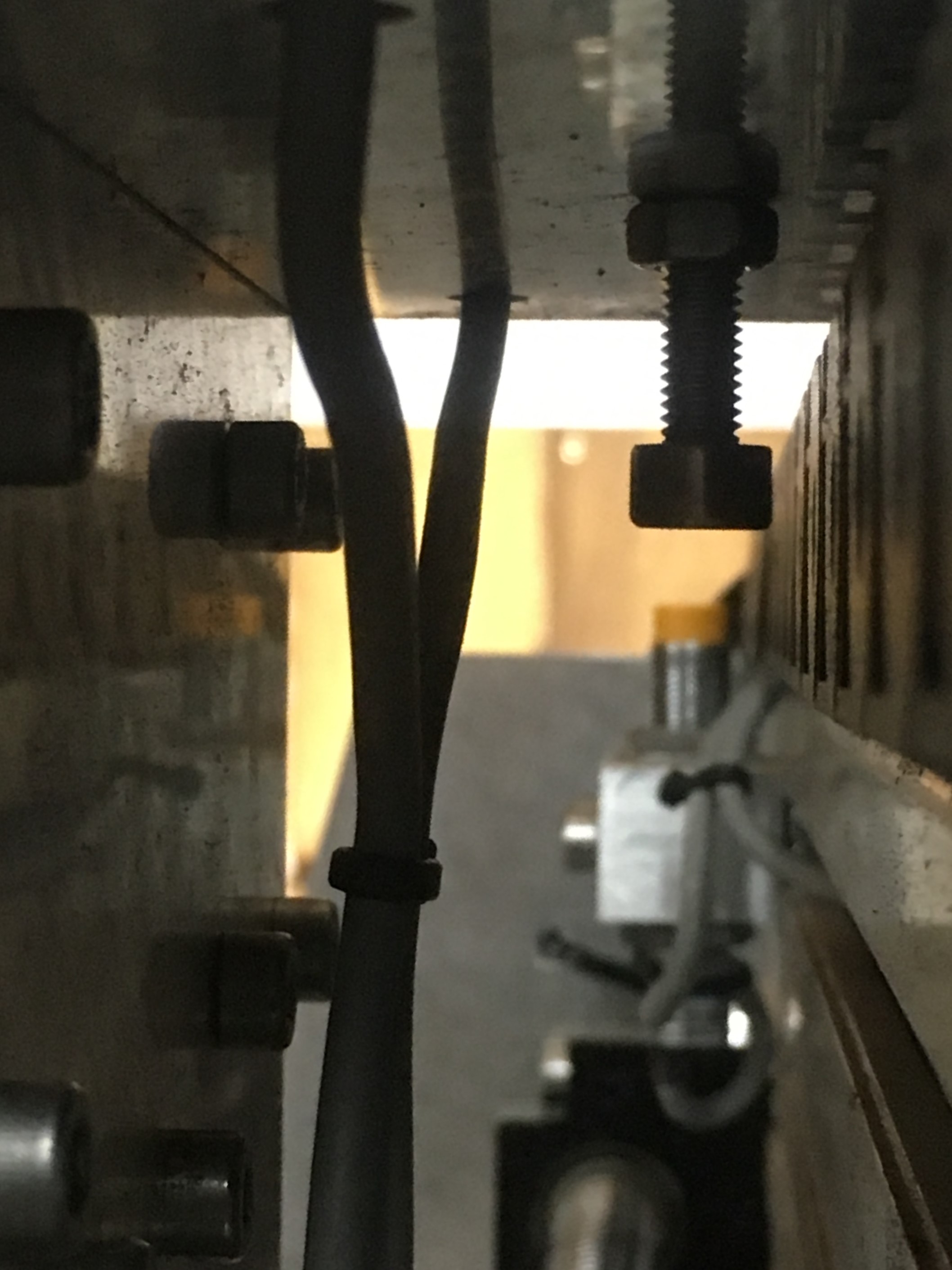
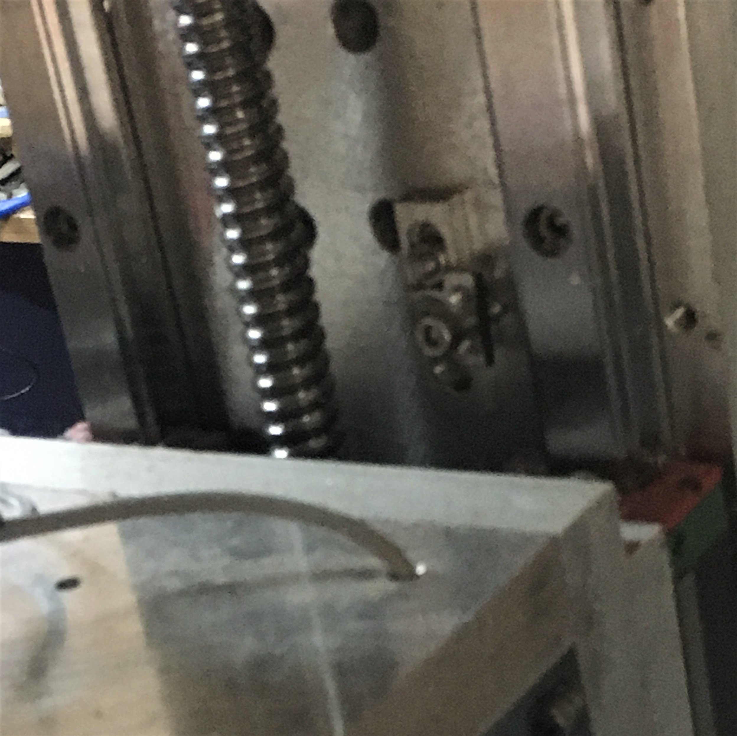
Y-- -Limit (=Y-Home) sensor (background) below the working
table with corresponding screw (foreground).
The screw is mounted on the lower gantry cross bar.
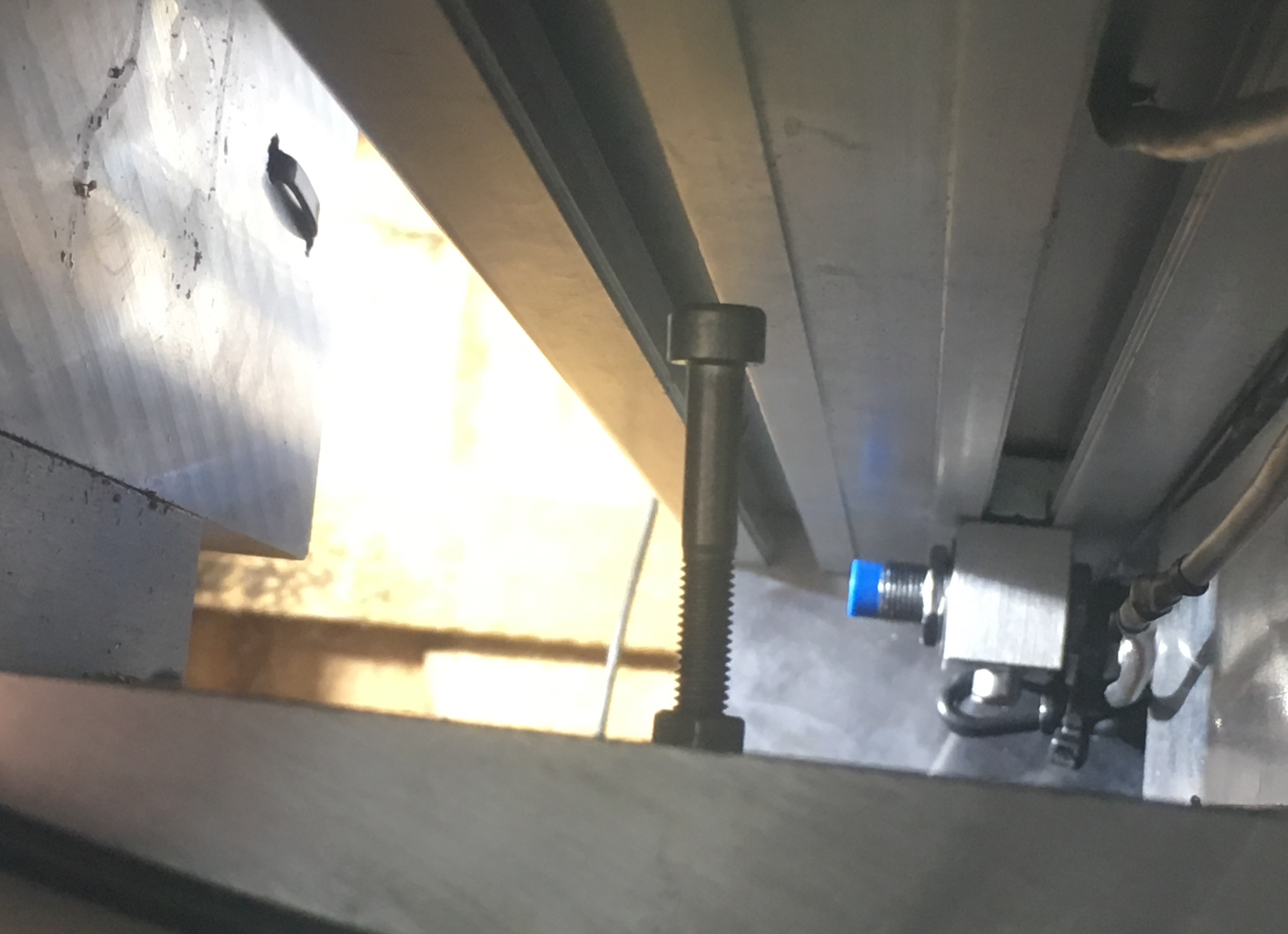
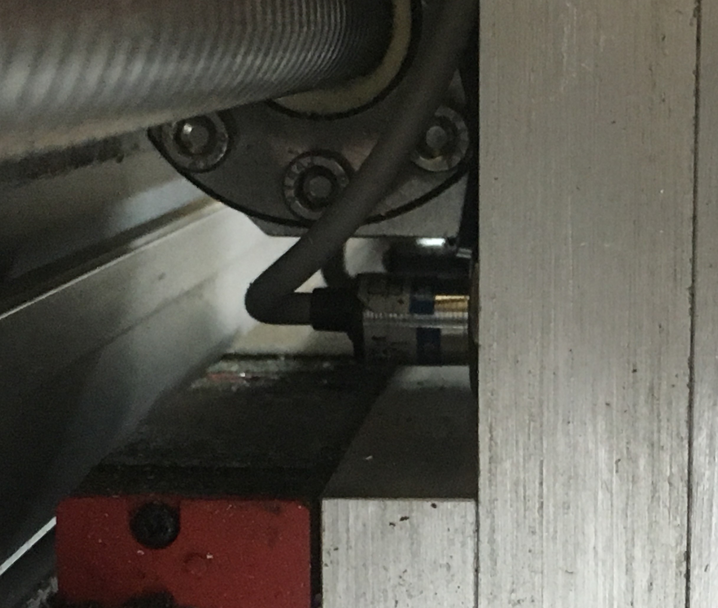
Z--Limit sensor (left image) mounted on the gantry wagon and
corresponding screw (right image) adjustable mounted on the Z-Plate.
The Z++ sensor is mounted in the same height as the Z-- sensor (covered by
the Z-- sensor in the image).
Its corresponding screw is mounted on the lower end of the Z-Plate.
The left (X--), rear (Y--) and upper (Z++) sensors are not only connected to the limit entries of the DDCSV but also (with a wire jumper) to the home entries of the controller to not only serve as limit- but also as home-sensors.
Since I used NPN sensors, I had to set the "effective electric level for X-- ..." (#60..62, #408..#410 and #412..#414 of DDCSV) to high.
To use the left/rear/upper limits of the machine also as home position, parameter #51 (Enable limit signal when home) was set to "Disable".
The sensors proofed to be exact within a view hundreds of a mm. More than exact enough to deal as references for the tools in the tool holder.
--> Continue with Auto tool change spindle