DIY build of a gantry milling machine with standalone controller and auto tool change
Auto tool change spindle
"As rigid as possible" and "as cheap as possible" was the motto when
I started to build my CNC. As a logical result I ordered a typical 2.2kW air
cooled China spindle. Including an VFD the price (300€) was fantastic. I used it
and it was okay.
But changing tools takes a while with this device - not only the mechanical changing, also the height measurement of the tool after every change takes time and is a possible source of errors. As a result I tried to minimize the number of tools needed for a specific design - not what I really wanted.
The ATC Spindle
Than I saw a video on YouTube with a ATC (Automatic Tool Change) spindle driven by the DDCSV controller - motivated by this the ambition grew to do the same - in contrast to my "as cheap as possible" aim. Finally I found an affordable ATC spindle, which had quite a good reputation in the internet community: the JGL-80/2.2R30 2.2kW water cooled spindle from Jianken for ER20 holders. I ordered it by Alibaba.com and had a very nice contact to Wafer, who was responsible for me at Jianken. Price for the spindle incl. shipping was 1550$, not including import taxes to Germany - not exactly cheap but worth its price.
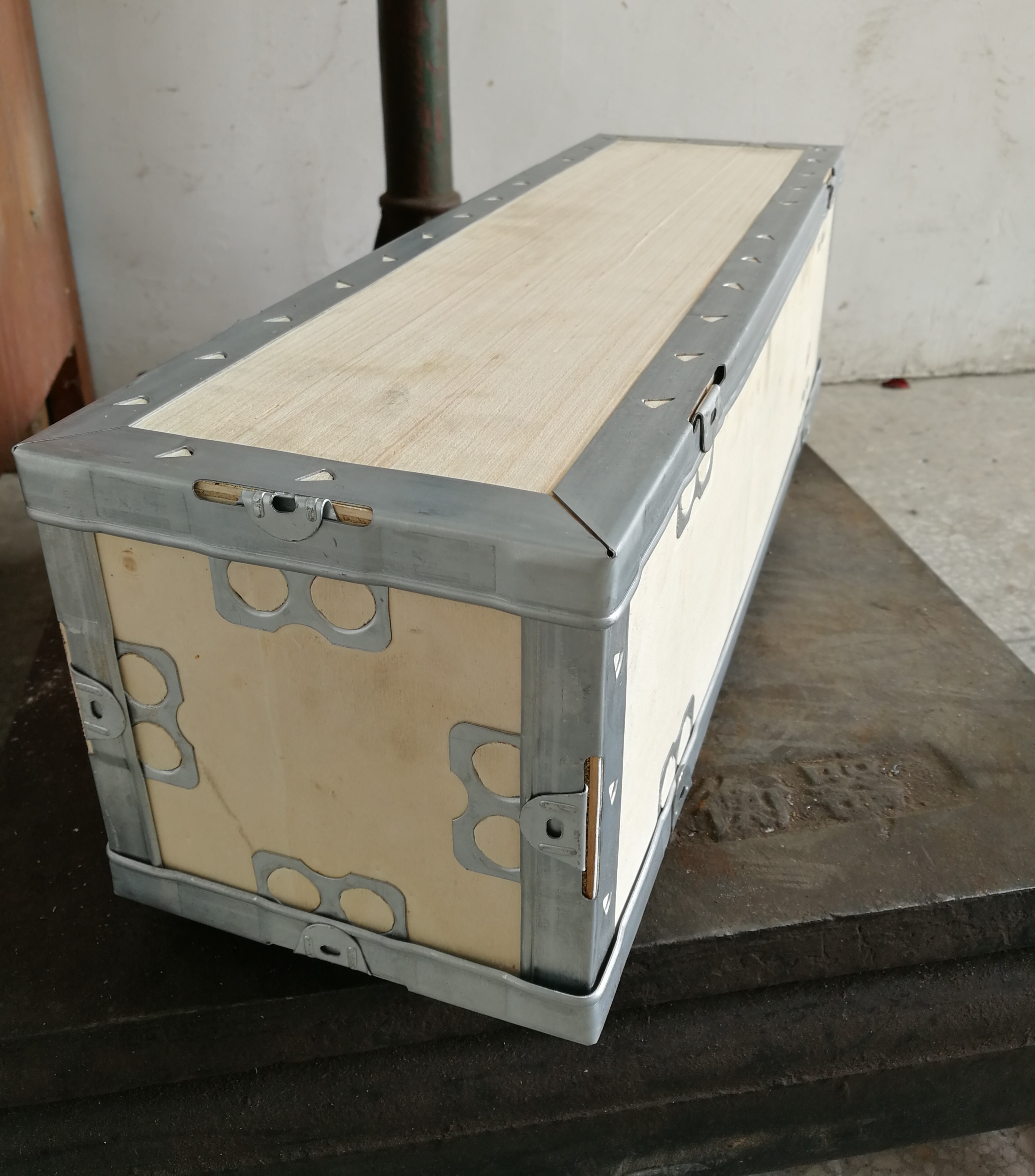
My ATC in the box (image sent by Wafer before shipping)
Since the diameter of the new spindle was identical to the "old" one, fixing it at the Z-axis was easy. In contrast to the old one, which had a nice plug for power supply, the new one was equipped with a bare cable. I did not find a socket compatible to the old one in the web und finally ended by ordering two heavy duty plug/socket combinations. One to connect the new ATC to the existing cable, the other (only the plug) for an adapter cable together with the socket of the old spindle. With this adapter cable I can use the "old" spindle as a back up.
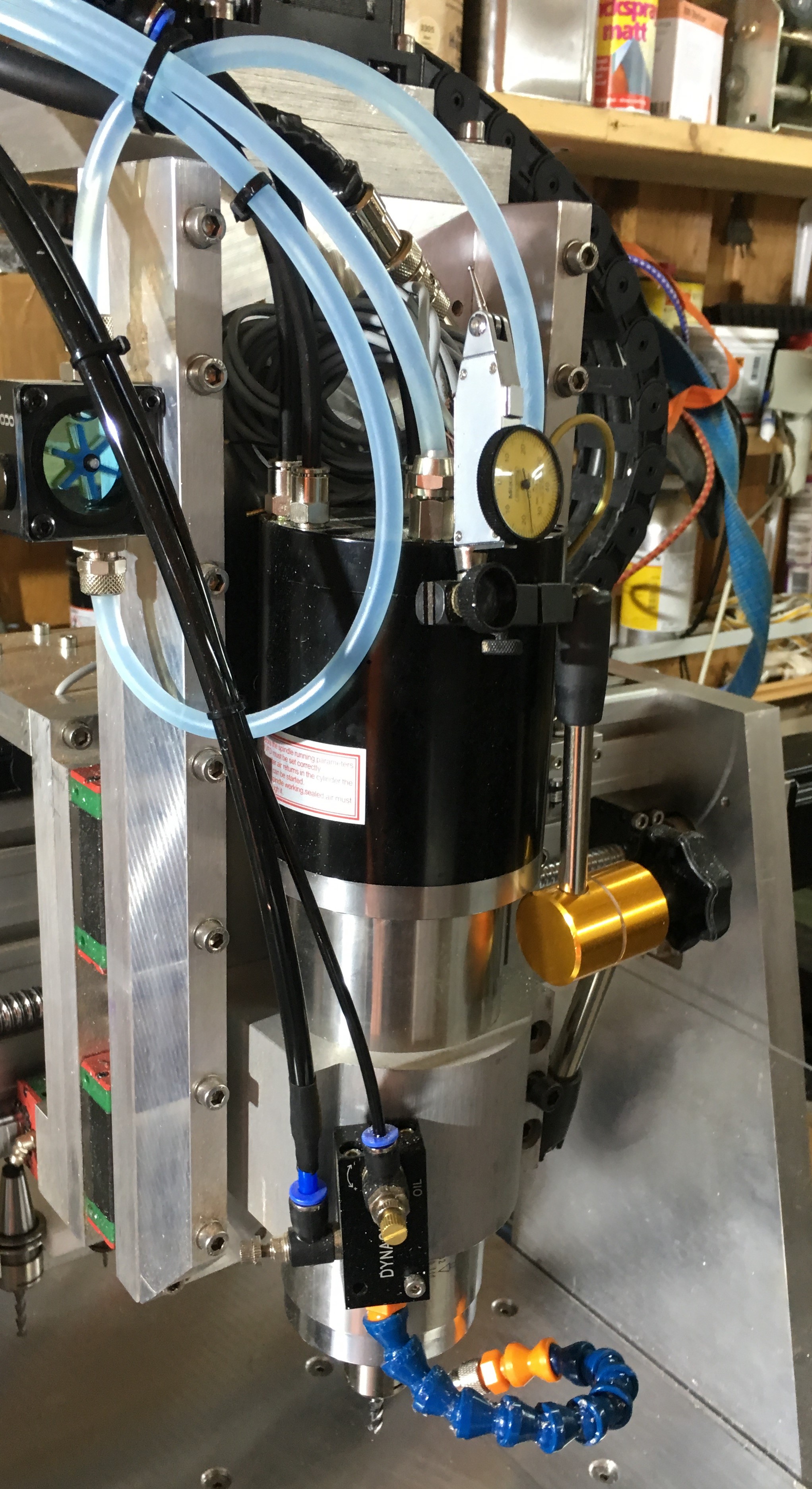
The image above shows the spindle finally mounted to the Z-Axis. Right to the spindle the orange holder of a puppy dial gauge is visible. The gauge is permanently mounted to the Z-Axis to have quick access during workpiece setup. The light blue pipes are responsible for the water cooling of the spindle. They are fed through the energy chains into a 30l plastic can below the machine. A small 24V oil pump in the can is responsible for the circulation. The small impeller indicator on the left side rotates slowly when the water is running.
In addition to the two water pipes, four air pipes had to be added to be connected to the ATC. Two to drive the tool change cylinder (one to loose it, one to fix it) one for the air which is blown through the tool holder chuck during tool change (to clean the chuck and the ER20 holder) and the last for "seal air". This seal air is used to protect the ceramic ball bearings from getting in contact with dust. Seal air is switched on/off together with the spindle itself by a solenoid valve, which also switches the coolant air on and off. The valve is activated by a relay of the VFD (see below) which is "connected" to the M3/M5 output of the DDCSV.
In addition to all this pipes and the motor power cable, the spindle serves to other cables, which I currently do not use. According to Wafer (the Jianken women) "one is to detect if the tool holder is really clamped, and the other is to detect if the tool holder is really completely released." In the PDF-documentation she sent me, only one them is described. I think, some inductive sensors are used inside the spindle. If this sensors are capable to detect, whether or not a tool holder is inserted (and not only, whether or not the internal clamps are open/close - which is possible also in the absence of a tool holder) their usage can be very sensible - for detecting faults during tool change and also to detect the situation after manual tool changes (see below).
The VFD
Together with the "old" spindle I ordered a VFD (Variable Frequency Drive) inverter of type Huanyang HY02D223B (see here for documentation).
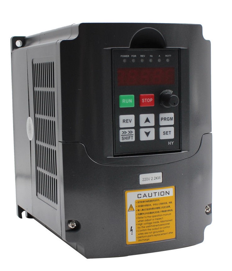
This VFD has a power output of 2.2kW and a maximum rpm output of 20000, what is also the maximum rpm of the old spindle. The ATC spindle can do up to 30000 rpm, which I currently can not use (and I think, I do not need until I will do big projects with extreme small mills...).
The VFD can be configured in a wide range. To be honest: I think, I can tune the performance of the ATC-VFD combination a lot, but until now, I didn't. If anybody has done it in respect of momentum and power of this concrete ATC-VFD combination, please let me know.
I connected the DDCSV VSO output to the VI input of the VFD to be able to control the rotation speed by G-Code and set up the VFD accordingly (PD002 of VFD set to 2???) - with the result, that the speed control knob of the VFD is useless ;-). By connecting the FOR input of the VFD to the M3/M5 output of DDCSV, the spindle can be switched on/off by G-Code (set PD001 of VFD to 1). Finally I used the FA/FB connection of the VFD as a switch for the 220V solenoid valve, which switches the coolant air and ATC seal air on/off. (Set PD052 of VFD to function 1 "Run") - don't forget to connect DCM and ACM of VFD to GND of DDCSV!
I tuned the acceleration and deceleration time of the ATC within the VFD but was not satisfied especially with the deceleration time. Since the tool change can only be performed, after the spindle stopped turning completely, tool changing may be faster if the deceleration time is shorter - especially if the spindle is near the tool holder of the current tool when a tool change command is started - the time to move to the tool position is short in this situation. My idea was to add a break resistor to the VFD, since it has plugs for it and it is described in the manual. Far from it! The plugs are connected to nothing internally. Some googling resulted in the idea, that it would be easy to add the missing components (since the controller board of the FVD has the layout for the break resistor controlling components, which are simply not populated). After ordering the components from China and receiving them some weeks later, I dismounted the VFD from the control cabinet and opened it to solder them. Far from it again! It seems, Huanyang did change the controller layout - no place for the components at all! I finally gave up - if anyone is interested in a break resistor, a power IBGT and an opto coupler, let me know...
The tool holder
Manual tool change
Automatic tool change
Things to do
--> Continue with IO-Expansion of the controller