
DIY build of a gantry milling machine with standalone controller and auto tool change
Overview
This site focuses on the electronic parts of the CNC - the mechanic is not described in much detail. I think, there are enough other sources on the web dealing with this.
So, only some short words about the mechanics.
The machine was build "around" a cheep eBay-offer: three pairs of 20mm linear rails (400mm,700mm and 1000mm long), twelve HGH20 carriages, three ball screws (also 400mm, 700mm and 1000mm long) as well as couplings, nut housings and BK/BF12 holders. All together for less than 400€. Here the eBay link. (To be honest: I bought it via AliExpress in 2017 - even cheaper, but I did not find the link any more...)
The entry point for the build: cheep all in one mechanics
Not really high quality, but okay for my purpose. I used them as shipped except two things:
- The BK12 blocks where equipped with normal bearings, which are less than
suboptimal to deal with the forces in axis direction without mechanical play.
I replaced them with pairs of angular contact ball bearings 7201 and some shims
between them.
- The three 8*10 couplings did not fit to the axes of the chosen motors so I had to buy three 10*14 couplings.
Due to the length of the linear rails the dimensions of the machine was more or less defined: 1000m deep (y), 700mm wide (x) and 400mm high (Z).
700mm width is okay to fit through a normal door, if the added extensions are not too big ;-) Since the X-driving motor is added on the right side of the machine, this has to be demounted, if needed. For this reason the cable connections are pluggable.
Motor to be demounted to fit through "normal" doors

The main structure of the CNC:
The working table:
The working table is constructed fro 80mm*80mm aluminum extrusion bars (two
in length directions (Y), four in X-direction). All connected with heavy duty
aluminum angles.
The front and back are covered with two 15 aluminum plates. The serve as
- holders for the Y-Blocks
- Holder for the Y-Motor
- "Legs" of the table
- Holder for the controller
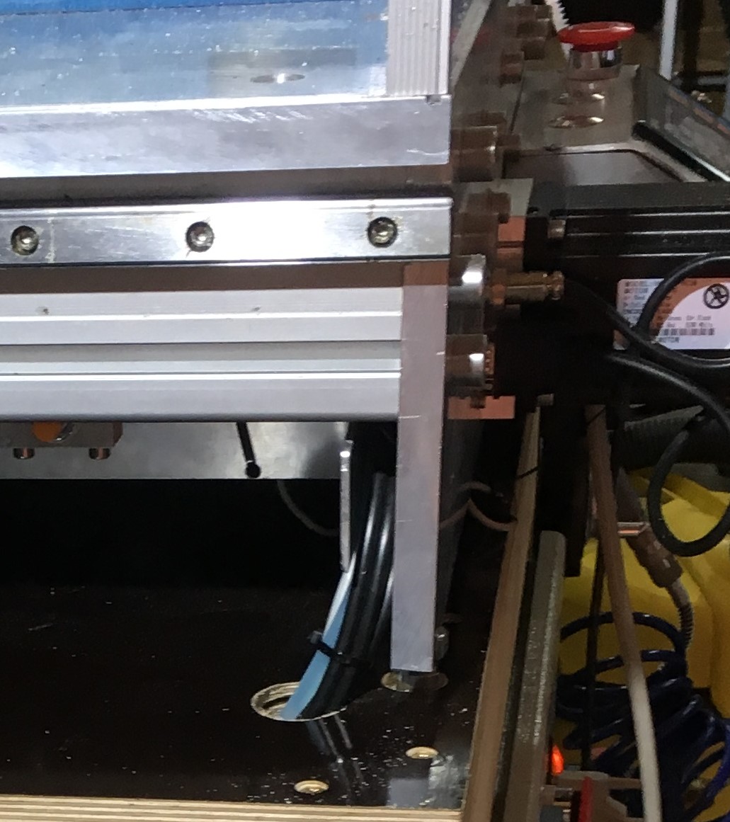
The driver for the gantry (Y-direction) below the working table resulted in some distance between the table and the lower cross bar of the driver. This distance is used to feed the cables of the gantry trough two energy chains to the left and right edges of the table.
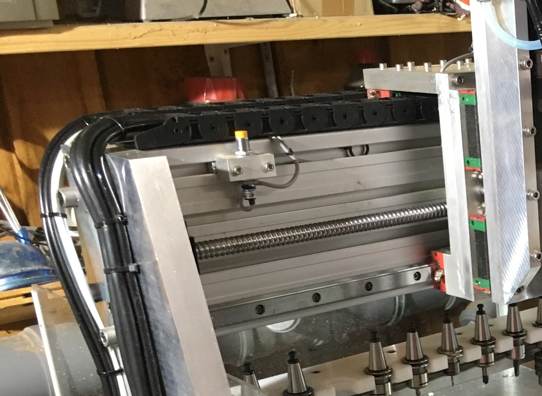
View below the working table with two energy chains left and right to the Y-ballscrew. They feed the cables from the gantry (right image) to the front cover plate.


Just behind the front cover plate, two 50mm holes are drilled in the supporting wagon, where the cables are feed through to be connected to the control cabinet. As a result of this "moving the cables behind the scenes" all the cables and tubes are more ore less invisible.

The working table is covered by a massive 20mm aluminum plate (~1000mm*700mm), which holds the machine vise. Until now, no hole matrix or groves are machined in the plate - this will be done "on demand".
The gantry:
The gantry is constructed out of 30mm plates for the left and right side and an 80mm*160mm aluminum extrusion bar (1000mm length) to connect them. This heavy construction resulted in a stiff gantry - the only draw back is it's mass, which has to be accelerated... The 20mm linear rails in Y-direction may be a bit small to carry this construction - may be, I'll exchange them in future - until now they work fine.

To get the biggest possible distance for the X rails on the gantry, one is put at the lower edge of the gantry bar, the other is put at the top. The top of the bar also serves as a bed for the energy chains, which surround the upper carriages.
The Z-axis:
 |
The main parts of the Z-axis and it's connection to the gantry are build from 20mm aluminum plates. Design goal was to get the spindle as near to the gantry as possible. The Z axis motor is carried by the Z axis, not by the X axes. The advantage of this construction is it's simplicity. The drawbacks are higher mass to be moved by the Z axis and a bigger construction height. Another design goal was to make the Z wagon as narrow as possible to get an X working range as big as possible. As a result, the flanges of the spindle holder (which was sold together with the Non-ATC spindle I used first) had to be cut away. New threaded holes were drilled directly in the backside of the holder and the screws fixing it to the Z plate have to be be fixed from behind (which is easy, if the spindle is moved down). After the Z-Axis was done, I found a DIY gantry CNC on the web, which uses a box surrounding the gantry bar as base for the Z-Axis. This box is driven in X direction on the opposite site of the gantry bar. A clever idea, since the distance of the spindle to the gantry can be reduced by some centimeters - too late ;-( |
--> Continue with Stand alone controller DDCSV 1.1